Part 1: OpenGL
Motivation
In this series of posts, I'll try to simulate waves on a GPU using CUDA.
First, I'll describe the exact scope of the project. The goal is to implement some computational fluid dynamics method to solve some fluid dynamics problem - for now, let's take the upstream finite-difference scheme for the advection equation, because it's one of the easiest setups I can think of. The method will be implemented on the GPU using CUDA. There should also be some sort of visualization to ensure that the results are sensible, but it can be rather basic.
One thing that is not a goal is rendering photo-realistic waves. I know that this is possible on a GPU, and I might look into it more once this project is finished, but for now this is outside my scope.
As a first guess, the steps of the implementation will be as follows:
basic project setup with a C++ main function, CMake, defining the data structures, and a very basic simulation loop.
getting some visualization of the results
find some numerical method and how to implement it in CUDA
couple the numerical solver in CUDA with the rest of the project
implement more difficult methods, equations, and boundary conditions (possibly using config files)
Once I actually started the project, the first step turned out to be very straightforward, while the second step turned out to be much more difficult than I thought. However, it was also very instructive - I effectively learned the basics of OpenGL. So this first post is going to focus on the first two steps and is essentially an introduction to OpenGL. Once this is done, I will focus on the actual "waves on CUDA" part and write the results in a second post.
The code is version-controlled (of course) and publicly available on my GitHub: https://github.com/Warggr/waves-on-cuda/ . A lot of content is copied and commented here, but often (more often in the later parts) I will just write here a summary of what I did and why. If you want to learn more, I will point you to my repository and some tutorials that I (mostly) followed.
Basic infrastructure without CUDA
I define the minimum viable product as follows:
C++ code to define a 2D surface on which waves can travel
some wave movement
wave visualization
The first two should be pretty straightforward. The second will require a front-end library. I'll use GLFW as I've seen it used in a similar project in a lecture; there are probably some better choices. GLFW is based on OpenGL, which is a cross-manufacturer graphics rendering interface. You might say "why use OpenGL if this project is going to be specific to CUDA/NVIDIA?". I could actually use (some CUDA-specific GL) for graphics rendering as well, but for now I'll use CUDA only for the fluid dynamics part.
Basic C++ code
Let's jump into the C++ code. Here's a simple grid with 100x100 double cells, all initialized to 0 (put this into a file called src/grid.hpp):
#pragma once
#include <array>

constexpr int GRID_WIDTH = 100,
    GRID_HEIGHT = 100;

struct Grid {
    std::array<std::array<double, GRID_WIDTH>, GRID_HEIGHT> _data;
    Grid() {
        for(auto& row: _data) {
            for(double& cell: row) {
                cell = 0;
            }
        }
    }
};
During simulation, we're going to compute the state at time step n+1 based on the state at time step n - so we need to store both. For now I implement a super simple time scheme where the fluid travels exactly once cell each time step, and the boundary condition is always 1 (i.e. we'll have a wave of 1 going from the left to the right, with the grid being 0 outside the wave).
#pragma once
#include <array>
#include <utility>

struct Grid {
  ...
}

class World {
    Grid grid1, grid2;
    Grid* current_grid, * other_grid;
public:
    World() {
        current_grid = &grid1;
        other_grid = &grid2;
    }
    void step() {
        for(int i = 0; i < GRID_HEIGHT; i++) {
            (*other_grid)[i][0] = 1.0;
            for(int j = 1; j<GRID_WIDTH; j++) {
                (*other_grid)[i][j] = (*current_grid)[i][j-1];
            }
        }
        std::swap(other_grid, current_grid);
    }
};
To iterate over Grid objects as the code does, we'll need to implement a few methods on the Grid (the const version of the iterators are going to be useful later):
struct Grid {
    using GridArray = std::array<std::array<double, GRID_WIDTH>, GRID_HEIGHT>;
    GridArray _data;
    Grid() {
        for(auto& row: _data) {
            for(double& cell: row) {
                cell = 0;
            }
        }
    }
    GridArray::iterator begin() { return _data.begin(); }
    GridArray::iterator end() { return _data.end(); }
    GridArray::const_iterator begin() const { return _data.begin(); }
    GridArray::const_iterator end() const { return _data.end(); }
    std::size_t size() { return _data.size(); }
    std::array<double, GRID_WIDTH>& operator[] (int i) { return _data[i]; }
};
(at first I forgot to return a reference (&) in the operator[] - so it didn't work because it always modified a copy of the grid - make sure that doesn't happen to you :) ) Now let's create these files: src/main.cpp
#include "grid.hpp"
#include <iostream>

int main() {
    World world;
    for(int t = 0; t<50; t++) {
        world.step();
    }
    for(const auto& row: world.grid()) {
        for(const auto& cell: row) {
            if(cell > 0) std::cout << cell;
            else std::cout << "  ";
        }
        std::cout << std::endl;
    }
}
I then compile the project using CMake (I'll leave out the steps because all of it is boilerplate) and get, as expected, a front of 1 's advancing from the right. The program is now good enough to be committed (commit).
Integrating GLFW
I have GLFW installed, so I'll use the local version. A later TODO would be to fetch it if not already installed.
CMakeLists.txt:
cmake_minimum_required(VERSION 3.0.0)
project(waves_on_cuda VERSION 0.1.0 LANGUAGES CXX)

find_package(glfw3 3.4 REQUIRED)

add_subdirectory(src)
src/CMakeLists.txt:
add_executable(waves main.cpp)
target_link_libraries(waves glfw)
GLFW expects to be in full control of the program - you need to write your main loop as while(!glfwWindowShouldClose(window)) and call glfwPollEvents() regularly. However, I would find it cleaner to have GLFW not be in control of the program - the main loop should be the wave simulation, and then we pass the results to the rendering after each time step.
I think the cleanest solution is to run GLFW in a separate thread, the UI thread. We'll have a one-way channel of communication, a queue where the main thread posts events whenever a new simulation timestep becomes available, and a final event if the interrupt signal has been received. In the future, we might make the communication more complex to e.g. skip simulating time steps if the renderer is too slow. Having this setup has multiple advantages:
we decouple GLFW from the main program logic; if we want later to switch to another rendering (or have the option to choose rendering at runtime), this will be easy to refactor
we make no assumptions on whether rendering or simulation are faster; and we can make both as fast as possible (either the rendering will render multiple times the same simulation timestep, or the simulation will simulate timesteps that won't be able to be rendered).
Making GLFW work actually took a couple of hours as there were some bugs to fix. It turns out that GLFW keeps some thread-internal state, and you can't just initialize it in one thread and make it do something in another thread. Furthermore, you typically need an extension loader, such as Glad or GLEW (I used GLEW), which is also not quite straightforward to integrate. Finally, I wanted my assets to be compiled, instead of pasting OpenGL domain specific language as strings into the C++ program. Some more details on this in the following section.
Some links that are generally useful as introductions into OpenGL: Anton's OpenGL4 tutorialsThe GLFW quickstart guide
Compiled (SPIR-V) shaders
OpenGL uses so-called shaders for basically everything (perspective projection, transformation, coloring). They are essentially small functions that are loaded into the GPU and executed there. Shaders are written in a C-like language called GLSL. The easiest way of loading a shader looks like this:
const char* fragment_shader =
"#version 410 core\n"
"out vec4 frag_colour;"
"void main() {"
"  frag_colour = vec4( 0.5, 0.0, 0.5, 1.0 );"
"}";
GLuint vs = glCreateShader( GL_VERTEX_SHADER );
glShaderSource( vs, 1, &vertex_shader, NULL );
glCompileShader( vs );
I find this incredibly ugly for two reasons. First, you're pasting code as a string in a C program, so you miss all the benefits of e.g. GLSL syntax highlighting. This is rather easy to fix: you could load the string from a file. Pretty much all tutorials do that after they've taught you how to use strings.
Second, the GLSL code is compiled whenever you run the program. This means that if you have an error in it, you will only know at runtime of the C++ program. It would be much more convenient to compile it ahead-of-time.
It turns out that complete compilation is not possible, but it can at least be compiled ahead-of-time into an intermediary format called SPIR-V. More details and examples can be found here and here.
So I followed those examples and used SPIR-V shaders instead of GLSL ones. I therefore have another compilation step in the CMakefile. In Make adding a new type of target would be straightfoward - Make is agnostic to what language is used and how things are compiled - but in CMake, adding a non-C++ target needs the add_custom_command command:
function(compile_spirv in_file out_file)
    add_custom_command(
        OUTPUT ${out_file}
        COMMAND glslc ${in_file} -o ${out_file}
        DEPENDS ${in_file}
        VERBATIM # enables escaping; generally a good practice
    )
endfunction()

# see https://jeremimucha.com/2021/05/cmake-managing-resources/
compile_spirv(${CMAKE_CURRENT_SOURCE_DIR}/shader.frag fragment_shader.spv)
compile_spirv(${CMAKE_CURRENT_SOURCE_DIR}/shader.vert vertex_shader.spv)

add_custom_target(resources ALL DEPENDS vertex_shader.spv fragment_shader.spv)
By commit c7c3849, everything works and I have a GLFW window. So far the window displays precisely nothing, but it's already a good first step.
Displaying things with OpenGL
We'll follow Anton's triangle tutorials. As the name says, this is used to display a triangle; however, at the end of tutorial, he mentions that displaying a square can be done easily by replacing 3 by 4 in some places. I tried to display a square, but it didn't work, so I decided to display 2 triangles per cell instead.
When displaying the grid, the following question comes up: Are we using a finite volume method (i.e. each point in the Grid is a cell) or a finite difference or element method (i.e. each point is a node?) For now I will pretend they are cells. If we end up using a finite volume method, just pretend we're using the dual grid.
There are one fewer row and one fewer column of grid cells than there are nodes (we have 100x100 nodes and therefore a 99x99 grid of cells delimited by these nodes). Therefore, the list of triangles to display is an array
GLfloat triangles[grid_to_render->rows()-1][grid_to_render->cols()-1][2][3][3];
i.e. (rows - 1) x (columns - 1) cells, each cell having two triangles, each triangle consisting of 3 vertices, each vertex consisting of 3 coordinates. (At first I forgot the -1 and had some weird values displayed in the OpenGL window.)
We then pass the array to OpenGL and render them all using
glDrawArrays(GL_TRIANGLES, 0, sizeof(triangles) / sizeof(triangles[0][0][0][0])); //should be [0][0][0][0]
You will notice that sizeof(triangles[0][0][0][0]) represents one vertex (i.e. 3 coordinates), therefore the number passed to OpenGL is the number of vertices, not the number of triangles. At first I passed the number of triangles ( sizeof(triangles) / sizeof(triangles[0][0][0])) and was surprised why only 100x33.3 columns were rendered, instead of the 100x100 I was expecting.
We can add optimizations later - for example, right now each node is a vertex of 6 different triangles and is therefore passed 6 times to OpenGL. Maybe there's a way to optimize this (using an option called GL_TRIANGLE_FAN seems to be a possible solution), but I haven't found any easy way, so for now I stuck with the unoptimized version.
One improvement that is necessary, however, is perspective. Right now I don' t even see what vertices are at what height. Perspective is typically done using the vertex shader.
Tutorials such as https://learnopengl.com/Getting-Started/Coordinate-Systems usually do not have a fixed transformation in the shader; they pass this as a parameter to the shader. In shader language, this looks like this
#version 410 core
layout (location = 0) in vec3 aPos;

uniform mat4 view; // parameters
uniform mat4 projection;

void main()
{
   gl_Position = projection * view * vec4(aPos, 1.0);
}
It turns out that this is not possible when compiling for Vulkan - so I need to change it a bit, see here for more details and rationale. I also needed to bump up the #version to 420 because otherwise "binding" wasn't supported.
#version 420 core
layout (location = 0) in vec3 aPos;

layout(binding = 0) uniform Projection {
    mat4 view;
    mat4 projection;
} projection;

void main()
{
   gl_Position = projection.projection * projection.view * vec4(aPos, 1.0);
}
We need first to create these parameters (which are all represented as 4x4 rotation matrices) on the CPU, then upload them to the GPU. To create the matrices, the easiest way is to use glm, a header-only math library designed for working with OpenGL. The library and instructions on how to integrate it with CMake can be found here.
It turns out that the changes we made to the vertex shader affect also how we pass data to it. Typically, tutorials upload single parameters using a function called glUniformMatrix4fv; however we can't use it, because we have a parameter block, and therefore have to use another API called uniform buffer object (UBO). The UBO-related code can be found here.
Finally, adding a moveable camera (following the learnopengl.com tutorial) was faster and worked better than just trying to add a perspective on my own. Two notable changes between my code and the tutorial:
The tutorial is not object-oriented, while my code tries to do everything with the
MyGLFWobject. This is a problem for callbacks: GLFW callbacks must be functions, while I need them to be methods bound to theMyGLFWobject to access (and update) its attributes. In C++, we can't just get a bound method and use it as a function pointer (contrarily to Python, where I could just usesetCallback(self.callback)whereself.callbackis a bound method and can access all attributes ofself). The solution was to use the functionglfwSetWindowUserPointer(credits: https://stackoverflow.com/a/59633789) to associate the MyGLFW object with the window.I found the scrolling with the mouse, as suggested in the tutorial, unnatural, so I inverted the directions:
  yaw -= xoffset;
  pitch -= yoffset;
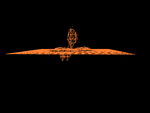
With this (commit 6701233), I have a good enough visualization that I can recognize what's happening:

(remember, we have a field that is 0 everywhere at first, and then a wave of height 1 enters from the right and moves leftwards for 20 timesteps - so this is exactly the visualization we were expecting). Now that the rendering is finished, I will be able to actually do some simulation / scientific computing. That will be described in a the next part.